
Enhancements and New Features Galore
Software: Logopress3 2018 Version
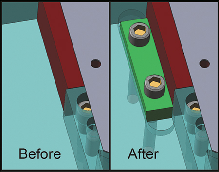 |
| Die designers can choose a predefined group of components and insert them along with all applicable fasteners and springs, and all pockets and holes are cut automatically with a single validation mouse click. |
For example, Logopress3 now can show, underneath the punches, the slugs that will fall though die openings. While performing a strip layout and defining cutting punches, it is common that the slug being cut does not match the exact shape of the punch, perhaps due to overlap with prior cutting punches. But it is useful to see the exact shape of the slug.
Once the strip layout completes, showing the strip size as well as tonnage required for the die, the designer can select a press for that die. With the new software version, the designer can select from a family of tool templates for a particular press and also customize the templates. This provides standardization among users and is helpful for new users who simply can select die parameters from a predefined database.
Similarly, as designers create a die they can choose a predefined group of components from another database and insert them using the new Logopress3 Insert a Set of Components command. Not only does this insert a group of components along with all applicable fasteners and springs, it also cuts all pockets and holes automatically with a single validation mouse click.
Also, Logopress3 die simulation and dynamic-interference detection has been expanded to include static interference. And, two types of motion have been added–traction and connecting rod/crank. These new motions benefit companies that create stampings using fourslide and vertical slideforming machines, as well as those running transfer dies. For ordering purposes, in the bill of materials, users now automatically can add an oversized machining allowance to the finished dimensions of the stock size.
Accurate Die Design Software: www.diedesignsoftware.com
New Functionalities for CAD and CAM
Software: VISI 2018 R1
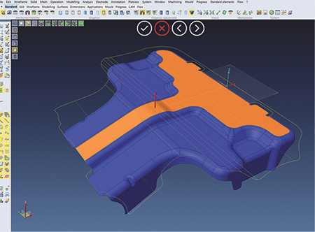 |
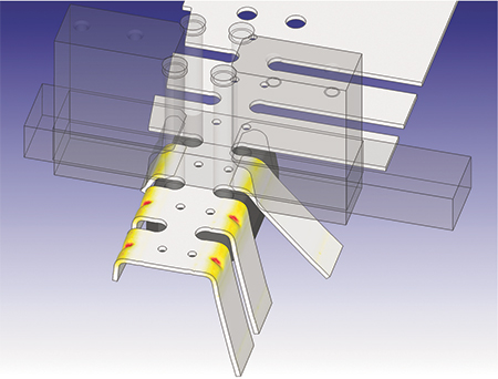
| Enhanced blanking functionality allows for managing constraint on a sheetmetal part by selecting a specific face, which also could have edges linked to other faces. Also, it is possible to define the face constraint in X or Y, or both, directions, useful should a designer wish to blank only specific faces of a model in step-by-step progressive-die design. |
VISI 2018 R1 introduces new sheetmetal developments in progressive-strip development and blank prediction, including the ability to manage constraints of specific faces of a blanked component. Designers also can define the face constraint in X or Y directions, or in both, particularly useful when looking to blank only specific areas of a model for step-by-step stage unfolding. In addition, the process of managing strip layouts using double-component geometry has been enhanced, thus reducing development time of a 3D strip design.
CAM developments include faster geometry preparation as well as an enhanced 2.5-axis chamfering strategy that provides many updates, including intelligent approach and retract points, advanced obstacle management, and speed improvement.
User-interface improvements to the CAM navigator enable showing of build-process status on the operation itself, allowing the process manager to be switched off if required. Tool-sheet reports have been updated, allowing users to benefit from enhancements to the software’s snapshot manager. In addition, for users requiring hole information generated from the feature recognition, the data can be exported to CSV files for external use.
Also, for improved quality control, a new VISI-to-PC-DMIS interface enables PC-DMIS to read native VISI CAD files directly, with annotations and points previously defined in VISI loaded automatically into PC-DMIS.
TST Tooling Software Technology, LLC: www.tst-software.com
Feasibility Early in Development Cycle
Software: AutoForm-StampingAdviserplus
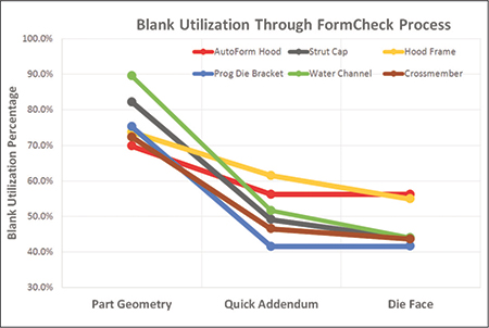 |
| This chart reveals blank utilization produced via different methods. Though relying on only part geometry and material can rapidly produce blank-size estimates, under- or overestimates at this stage can be very costly. |
Blank shape and dimensions are required submissions when stampers and die shops respond to RFQs. These early material estimates typically are made from experience gained on similar parts, process and equipment constraints, or simple unfolds of a 3D shape. But early estimates can carry strong risks. Underestimates can result in loss, and overestimates can lead to uncompetitive RFQs. Thus, the lack of accurate product and process feasibility at this stage can wipe out any profits.
It often is desired to determine blank size rapidly. The fastest method uses only the part geometry and material as inputs. But determining a blank size quickly without consideration for a process can be another source of hidden cost. The chart shows this for several parts. Each blank utilization is based on a different method. A rapidly produced blank size not matching the intended process can result in a large difference in blank size and, therefore, higher costs.
With little additional time, via the Quick Addendum method shown in the chart, a more accurate assessment of blank size and formability can be completed. Automatic generation of the blankholder surface and simple addendum geometry are possible with no real die-design knowledge, according to company officials, reportedly resulting in a more reliable blank prediction in comparison with a blank size based solely on part geometry. Further adjustments by the user help determine a more probable process while helping reduce blank size.
The last method shown in the chart, Die Face, shows a fully developed process and the matching geometry created using AutoForm-DieDesignerplus. At this point, additional process conditions can be explored to help determine ideal material utilization as well as formability. As seen in these example parts shown on the chart, the biggest change in estimated blank size results from the Part Geometry method compared to the Quick Addendum method.
All of these use cases require little time to complete via the software, according to AutoForm officials.
AutoForm Engineering USA: www.autoform.com
Automatic Springback Compensation and More
Software: eta/Dynaform Version 5.9.3
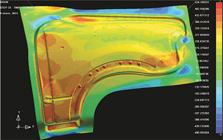 |
| Draw simulation reveals plenty prior to die build and final part design. Simulating the sheetmetal-forming process and analyzing the entire die system allows users to bypass soft tooling, reduce tryout time, lower costs, increase productivity and improve cycle times. |
Improvements in blank/trim-line development include combining the interface for blank and trim-line development to improve efficiency. Users can develop the blank outline and trim line simultaneously, develop partial blank outlines and partial trim lines, and develop a blank outline with a cut pattern.
The Auto SCP feature finds use for automatic springback-compensation iterations. When running the springback function, users first define the stamping stages—easily achieved using the step-by-step guided user interface. They then define the tool to be compensated, compensation zone, compensation method, scale factor and iterations for a customized and accurate result. The job is submitted and, when completed, the program automatically checks the springback amount and calls the solver to make a compensation adjustment for the tooling mesh. The compensated tool then replaces the original tool, and multi-stage jobs are rerun until the ideal solution is found.
Another helpful feature, the availability of process templates, allows designers to define forming processes for typical cases. For example, process templates can be used for a fender/hood inner or outer, roof/door inner or outer, lift-gate inner or outer, etc. Users can import and export to and from the saved template library.
Also, eta/Dynaform Version 5.9.3 offers a new license control with license roaming, allowing users to borrow a license from the server to use the software temporarily outside of the network. The new license control also supports a redundant license server within the network, which minimizes license-server downtime. Version 6.0, available by year’s end, will include a new interface.
Engineering Technology Associates, Inc.: www.eta.com
MFView Glossary of Metalforming Terms
See also: ETA (Engineering Technology Associates, Inc.), Autoform Engineering USA, Scientific Forming Technologies Corp., Accurate Die Design Software, Inc., LOGOPRESS
Technologies: Software