Coil purchase orders should specify the maximum allowable camber for each die process, or at least those most sensitive to camber. Otherwise, industry standard tolerances apply. If camber reaches beyond the specified limit, reject the coil. Without a specified camber limit on the purchase order, should camber fall within the limits of the applicable material standard, the press shop must learn how to run the coil. The cost and effort to run excessively cambered coils in production easily can exceed the additional cost for coils with restricted camber requirements.
 The best method to run coils with camber: Pilot the die. Every time the feed advances, the misaligned material will crowd one of the feed entry guides and the die. Adjust the crowded feed entry guide into the material, not away from it. This will push the coil back into alignment with the tool when the feed roll releases for piloting. The material will relax and recenter rather than accumulate the camber error.
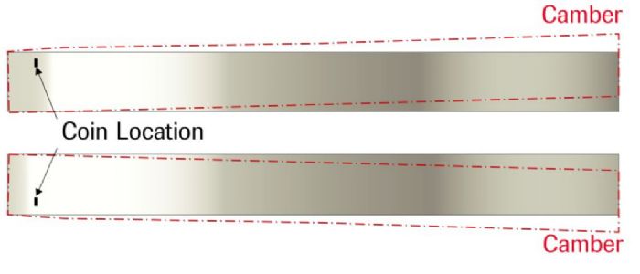
Another option: Coin a shallow chisel-point depression in the top surface of the concaved side of the coil strip in an area outside of the finished part or in the part carrier (Fig. 2). Coining the material will elongate the edge slightly to help even out the camber. The depth and location of the coining can be adjusted to suit the prevailing camber condition.
Sometimes a roller leveler—not to be confused with traditional straighteners—can be adjusted to apply additional pressure on the concave side of the coil to slightly elongate the edge and help reduce coil camber before the coil enters the feeder. This may work—assuming a feedline equipped with a roller leveler—on relatively thin coil strip, when incoming camber does not snake side to side, and on narrow-width coil.
Unexpected Sources of Camber
 When incoming coils fall within their specified camber limits, but camber appears or worsens as the material feeds into the die or during work on the strip, look for a few things.
First, verify that the straightener and feed unit have been maintained properly and are free from wear and damage. A bent or unevenly worn roll or a loose roll bearing can cause the roll(s) to tip in one direction. This causes uneven roll pressure across the width of the coil, which can induce camber in narrow materials and edge wave in wider coils.
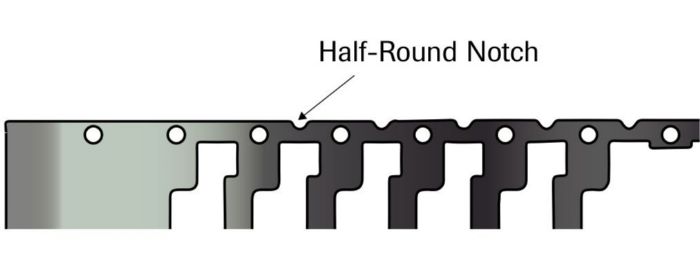
 Some die operations cause the progressive-die strip to camber due to cutting stresses and the relieving of internal stresses in the strip—prevalent in strips that carry parts on one-sided carriers requiring large amounts of gutting or cutouts. Adding a half-round notch in the carrier between the pilots can help balance the stresses (Fig. 3). The notching station should be adjustable for the initial die tryout, enabling movement of the notch depth inboard or outboard to achieve the desired results. The station then can be doweled permanently in place or left adjustable.
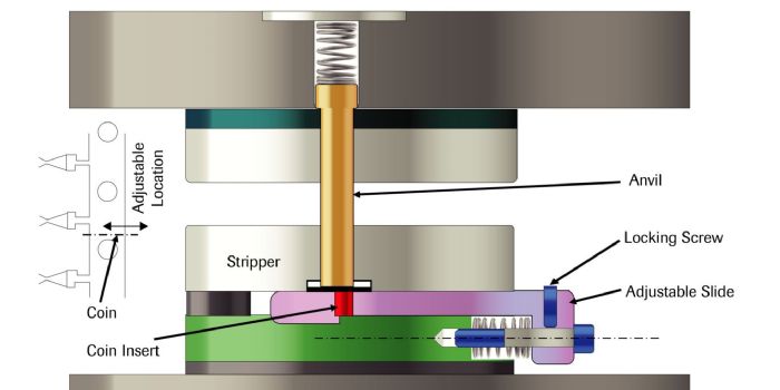
Another option for controlling stamping-induced camber: Add an adjustable coining station in the die that imparts a small chisel-point depression in the carrier (Fig. 4). This method proves useful in dies that run thin materials, such as those used to stamp electrical terminals.
Narrow, thin-gauge coils represent the most camber-prone materials. Incorrect packaging and storage of these coils also can induce camber, such as with several coils stacked vertically and banded together on a wooden pallet or skid. In production, the operator must lift the coils individually during coil changes, usually using coil separators between each coil. The separators must align properly. Misaligned separators and multi-skid stacks can cause coils to camber, even after a perfect slitting process. MF
Industry-Related Terms: Camber,
Center,
Coining,
Curvature,
Die,
Edge,
Feed Unit,
Notching,
Pallet,
Run,
Strips,
SurfaceView Glossary of Metalforming Terms Technologies: Tooling


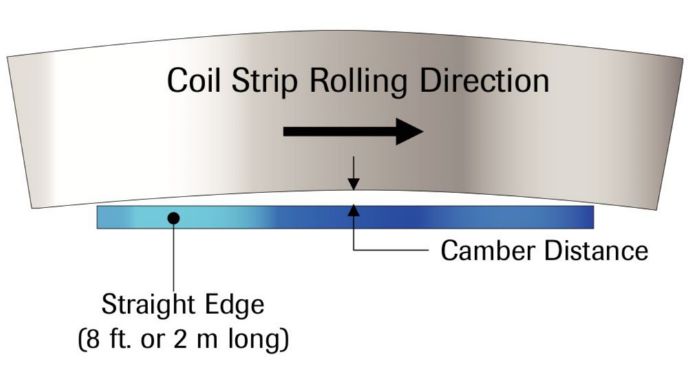 Camber occurs when one edge of the material measures longer than the opposite edge. In relatively wide coils, the longer edge may present as edge wave because the coil is too wide to curve sideways. In narrow strips, camber can be quite common, curving off to one side or even snaking back and forth.
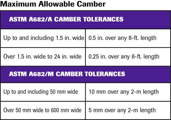 During slitting, unbalanced rotary-knife clearances on each side of the slit strip often cause camber. Different clearances affect the shear/fracture ratio on each edge of the strip. The edge with more shear depth will force curvature into the strip toward the edge with less shear.

 Webinar