100(D-d)/D = % reduction
For the above example, 100 (8.8 – 4.0)/8.8 = 54-percent maximum reduction. Hence, an LDR of 2.2 and a maximum percent-reduction of 54 percent represent the same amount of maximum cup drawability.
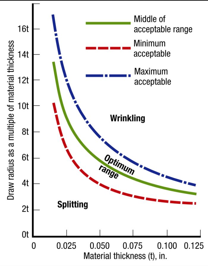
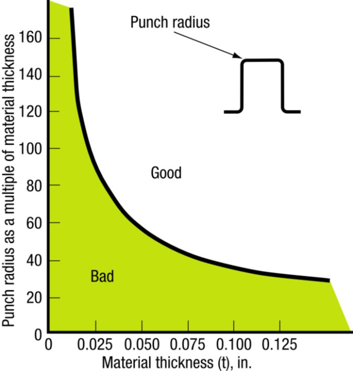
Do not consider the LDR measured in the laboratory as an absolute value that must be applied in the press shop. Like all forming operations, the product and die design represent two of many variables in the forming process. The LDR can be tweaked by proper design of punch and die radii based on sheet metal thickness. Figs. 1 and 2 illustrate recommended punch and die radii as a function of sheet thickness, respectively.
Redraws Often Required
 To achieve a robust process, die designers will not engineer draw dies right up to the LDR, as this makes the process susceptible to other variables. An LDR of 2.2 may be limited to a draw ratio of 1.9 for production purposes. Achieving a cup with a greater height-to-diameter ratio would require one or more additional redraw dies.
When redrawing operations are required, neither the shell diameter nor height approaches the final part-print dimensions during early draw stages—no need to use the part-print radii here. In fact, using a larger punch radius in the draw operation offers an advantage because the redraw blankholder fits inside of the drawn cup at this radius. This provides for a larger redraw radius on the blankholder, thus reducing bending and straightening loads for that operation.
The redraw-reduction percentage never reaches the percentage of the first draw reduction due to more bending and straightening forces in the redraw, a smaller cup wall in tension, and previous work hardening of the metal. Consequently, reductions for the first redraw usually measure 55 to 60 percent of the initial draw reduction.
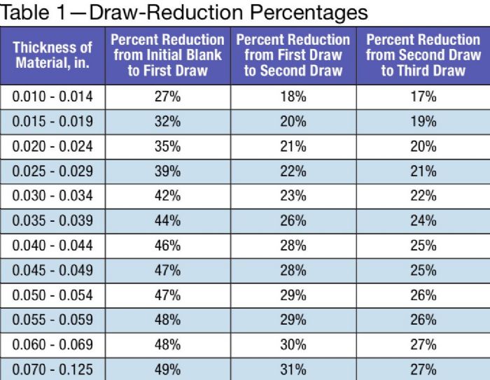
For example, given a first draw reduction of 48 percent, the first redraw reduction would be 48-percent initial blank reduction times 0.60, or a 29-percent reduction in diameter. The next redraw-reduction percentage must be less than that of the first redraw due to more severe workhardening plus an even smaller cup wall in tension. As a rule, any subsequent redraw reduction measures approximately 10-percent less than that of the previous redraw. So, given a first redraw reduction of 29 percent, the second redraw encompasses a 26-percent reduction; the third redraw, 10-percent less than the second, provides a 23-percent reduction; and the fourth redraw, 10-percent less than the third, a 21-percent reduction.
The Draw-Reduction Percentages table reflects this pattern, but different handbooks may provide slightly different reduction sequences. Keep in mind that most existing tables were developed empirically (trial-and-error) using a specific lubricant, material type and grade.
Optimizing Redraws
Suppose a necessary final reduction in the fourth redraw, but requiring only a 6-percent reduction. Building a fourth redraw tool for such a small reduction may not be cost-effective. Instead, a slight increase in the initial draw and other redraw percentages could eliminate the last redraw die at the expense of increased sensitivity to process variables (e.g., material thickness, yield strength, lubrication and friction, temperature, etc.). On the other hand, with the process already critical, reducing the initial draw and redraw percentages, and increasing the fourth redraw-reduction percentage, provide for a robust process.
Drawing Stepped Shells
 Deep drawing of stepped shells basically follows the same procedure as that for a cylindrical part. If the draw reductions for the adjacent steps fall within the allowable percentage, each step equates to the drawing of the corresponding cylindrical part, but with each redraw operation stopped part-way to establish the corresponding step height(s).
If the draw ratio of any two adjacent steps falls outside of the allowable draw reduction, the first draw must accumulate the required volume of material. The punch-nose radius for the first draw should end up slightly inside of the first redraw diameter. Subsequent redrawing proceeds the same as previously described.
Drawing Cone-Shaped Shells
When drawing cone-shaped shells, the ratio of the largest-to-smallest cone diameter and cone angle influence the LDR most. Cone angles less than 20 deg. usually can be approached as cylindrical draws.
Shallow cone shapes, with the ratio of height to the largest diameter (h/d) less than 0.30 and cone angles measuring between 50 and 80 deg., usually can be drawn in one step. For deeper cones, the relative sheet thickness (t/D) influences LDR to a greater extent than with cup drawing.
Drawing Spherical and Other Shapes
Difficulty drawing spherical shapes arises because of the high drawing load that must be applied to a very small contact area under the punch early in the stroke. Material stretches significantly due to the high tensile stresses, often requiring more redraws than for conical shapes. The use of variable blankholder pressure greatly facilitates the production of spherical shapes because a very high-pressure profile can be programmed early in the stroke to promote stretching, and quickly reduced to allow the blank edge to flow to create the cup wall.
Drawing parabolic shapes is more difficult than spherical parts. A height-to-diameter ratio of approximately 0.5 to 0.6 represents a nearly spherical shape, using the process as for spherical parts. Deeper paraboloids require very high restraining forces due to their high susceptibility to puckering―wrinkle formations across the punch face,―often requiring multiple draw reductions and the use of draw beads or lock beads to increase radial tension.
Axisymmetric cup drawing, the most predictable of all the metal forming processes, has the most known design parameters. Problems arise when overlooking or incorrectly applying these parameters. MF
Technologies: Tooling


 For example, let’s assume a maximum blank diameter of 8.8 in. and a 4-in.-dia. punch. Here the LDR would equal 2.2—simply stated, 2.2 to 1 as the maximum ratio between blank and punch diameters.

 Webinar