 Metal formers should consider two primary (and opposite) attributes when selecting sensors for die protection—precision and coverage. In some instances, sensors will need to detect an object in a precise place at a specific time; for example, to detect whether a strip feeds properly. In this case, stampers would use feed sensors, which require a high level of precision. At other times, they need to detect an object for which its exact position is unpredictable, such as an air-ejected part. Part-ejection sensors must provide detection over a larger area; thus, coverage takes precedence over precision.
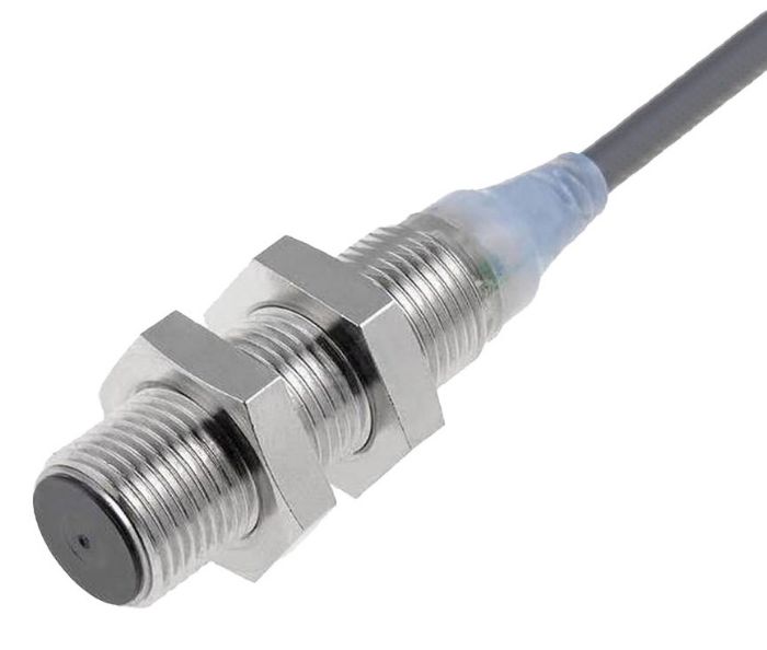 Whenever metal formers use photosensors to detect air-ejected parts, they should select ones that use infrared light. Sensors using infrared light offer better ability to ignore oil and lubricants than their visible-light counterparts. This is an important feature for detecting air-ejected parts.
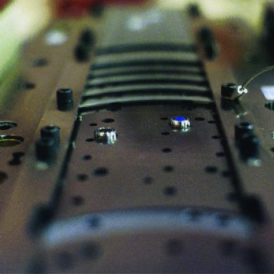
Feed Progression: Inductive-Proximity Sensors
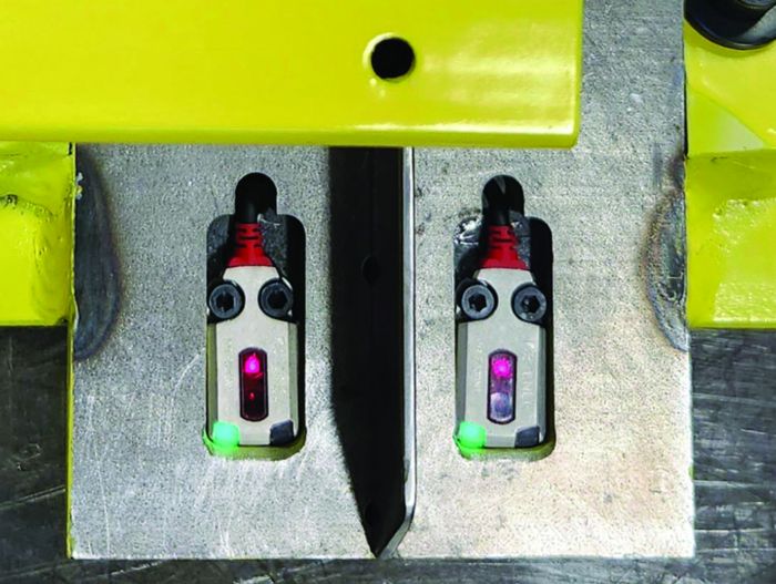
Of all commonly monitored die malfunctions, feed progression requires the highest level of precision. Inductive-proximity sensors perform best, as they can detect—without any physical contact—the presence of a metallic object. Typically, stampers install them in the lower die to detect a hole or strip’s edge, located so that the sensor will actuate only when the strip is in the proper position. Often, two of these sensors are needed to verify proper strip position. One sensor verifies that the strip has fed far enough (short-feed sensor) and another ensures that the strip has not fed too far (overfeed).
Material composition, alloy and any type of coating (plating, galvanizing) on the strip affect the proximity sensors’ detecting range. For that reason, test the sensors on a bench to determine their exact actuation point for the material being sensed, and then install the sensors accordingly. Once the actuation point has been established, these extremely precise sensors detect the strip with a repeatability of better than 0.001 in.
This high level of precision can be problematic if the sensors are misapplied. If sensors are installed so that they stop the press when the feed is off by 0.001 in., nearly constant nuisance stops will occur. Before installing proximity sensors, metal formers should first establish the feed tolerance. In other words, what is a misfeed, exactly? How much strip misalignment can be tolerated without stopping the machine?
 For example, setting the die to stamp 0.080-in.-thick material, the die setter determined that the pilots safely can align the strip if it is misfed by as much as 15% of the material thickness, or 0.012 in. They should install the short-feed sensor so that it will actuate only when the strip location is short by more than 0.012 in. They should locate the overfeed sensor so that it will actuate only when the feed is beyond its nominal feed length by more than 0.012 in. This provides a 0.024-in. window into which the strip must feed. Any modern servo feed or air feeder easily can maintain this tolerance.
Proximity sensors also detect the position of spring strippers at bottom dead center, where precision is required to detect pulled slugs—especially on thin material.
Material Buckle: Purpose-Built Electromechanical Sensor
Another aspect of feed-progression monitoring: ensuring that the material feeds properly into the die without buckling. If a material buckle were to occur, the short-feed sensor would almost certainly detect it—eventually. However, detecting a material buckle as early as possible gives the press maximum time to stop. This is best accomplished by installing a sensor on a magnetic base between the feeder and the die to detect if the material buckles up or down more than a prescribed amount. Some vertical motion is normal, but too much indicates a problem in the die.
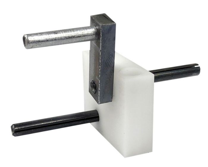
The preferred sensor for this detection is a true classic—the electromechanical material-buckle sensor. Its principle of operation: The sensor is a fork-shaped device with two tines. The die setter installs it so that the strip feeds between the upper and lower tines. The distance between the contact points is adjustable to allow for normal vertical movement. The fork is held in a plastic insulator with a single wire connected to the die-protection controller. When the strip feeds normally, no signal is sent to the controller. If the strip buckles up or down, it will contact one of the tines on the sensor. Because the strip is grounded, the sensor will cause the signal wire to short to ground, which the controller will detect and then stop the press.
For wide strips or to extend the reach of the sensor, the tines can be sized to accept standard spring probes.
The beauty of this sensor is its simplicity. It can be installed easily and the press operator can adjust it at run time. If nuisance stops ensue, operators quickly can adjust the distance between the tines with tools.
No Need to Reinvent the Resolution
One of the benefits of die-protection sensors is their versatility. By stocking just a few different types of sensors, metal formers can detect many die malfunctions. But as noted above, specific sensors are proven performers for certain applications. Rather than reengineering each individual solution, it is more efficient to bet on a sure thing and take advantage of these stalwarts by stocking them in ample supply for those applications. MF
Jim Finnerty is product manager, Wintriss Controls Group, LLC, Acton, MA. He created the Wintriss Die Protection Clinic, providing die-protection and in-die sensing information and training.
Press Controls and Sensors Series, Part 3: Best Practices for Die Protection
Press Controls and Sensors Series, Part 4: Die-Protection Troubleshooting: Three Cases Explored
View Glossary of Metalforming Terms
See also: Wintriss Controls Group LLC
Technologies: Sensing/Electronics/IOT
Comments
Must be logged in to post a comment. Sign in or Create an Account
There are no comments posted. Sensing/Electronics/IOT
From Data to Decisions: How Smarter Factories Will Shape Man...
Matthew Heerey March 13, 2025