Avoiding the 7 Deadly Sins of Stamping: Part 6; Using the 10% Clearance Rule for Every Type, Grade of Sheet Metal
April 25, 2025Comments
I’ve probably been in more than 100 die building and metal stamping shops, and conducted training at many of them. Still, to this day, when I pose the question: “What kind of clearance or punch-to-die spacing do you use for your metal cutting operations?,” the dominant answer is “10% of the material thickness.” When I ask why they use this value, the typical reply is: “That’s what we’ve always used,” or “The person who taught me the trade told me to use this value.”
While the 10% rule might be the ideal value for certain metal alloys and applications, relying on this value exclusively may create a plethora of other problems. Those include premature punch breakdown, poor tooling life, excessive stripping pressure and higher cutting forces—not to mention increased burr generation. It’s important to examine the physics behind metal cutting and understand when to use smaller or greater cutting-clearance values.
History of the 10% Rule
The 10% rule dictates that you determine the clearance, or spacing to allow between the cutting punch and the lower die, based on 10% of the sheet metal thickness, no matter what that is. In other words, if material is 0.100 in. thick, then the clearance between the upper cutting punch and the lower die is 0.100 in. or a value equal to 0.010 in. on each side of the cutting punch.
This rule was established during a time when higher-strength and exotic materials were not readily available. This is especially true in the influential automotive industry. In earlier times, vehicles were made primarily of steel. If a part failed during testing, the pressroom staff simply would increase the material thickness to improve the part’s appearance. Fuel economy and the car’s weight were not big issues.
The weight of a body-in-white of a 1950s car would average 1500 to 2000 lb., whereas modern cars typically range from 800 to 1200 lb. depending on the model and materials used.
When formed from aluminum, the average body-in-white weighs 500-1000 lb. To achieve those lower weights, higher-strength, thinner materials must be used. These newer materials behave much differently than the older, low-carbon steel grades; therefore, they often require much different metal-cutting clearance values.
I usually tell my training attendees: “This ain’t Kansas anymore, Dorothy.” The materials used today are not the same as those used 60 yr. ago. That said, using the 10% rule means the likelihood of missing opportunities for tool improvement. However, if all of the products and dies that you’re manufacturing are made of low-carbon and medium-carbon steel, the 10% rule probably remains the correct value.
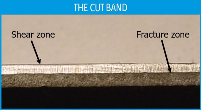 To understand the factors that affect the cutting-clearance value, first understand the basic dynamics of metal cutting. Metal cutting in a die is the most severe metal forming operation that you can perform in a tool. That’s not a typo: I did say “forming operation.” During the first stages of cutting, the material is deformed, or cold-extruded from the rest of the part or strip. This edge deformation is what toolmakers typically call the shear or burnished portion of the cut edge; the shiny portion is often referred to as the “cut band” (Fig. 1). This represents the forming part of the operation.
  The approximate tensile strength of low-carbon steel is double the yield value, whereas, new materials, especially high-strength steels, have yield strengths that are much closer to their tensile strengths. This means that very little deformation can occur during cutting before these materials fracture. Increasing or decreasing the cutting clearance also can affect the amount of resulting shear and fracture. Typically, as the cutting clearance decreases, the amount of shear increases. Conversely, when the amount of clearance increases, the shear distance decreases and the amount of fracture increases.