Deep Drawing in Progressive Dies
July 12, 2021Comments
Designing a progressive die always involves cost pressure to produce the part with a minimal number of die stations. On the surface, this seems logical because a die with more stations requires a longer die set, more tool steel, more machining and additional assembly time. However, the costs associated with an additional die station can pale in comparison with unrelenting downtime, scrap and effort required to keep a marginally performing process running over its lifetime.
 A primary cause for deep drawing failures in progressive dies: One or more draw reductions exceed the allowable percentage that the blank, or previously drawn shell, can be reduced without splitting. This allowable percentage varies with sheetmetal thickness. For example, for a deep-drawing-quality steel blank, the percentage of reduction for the first drawn-shell diameter varies from 32 percent for 0.015-in.-thick material to 48 percent for 0.125-in.-thick material.
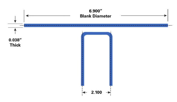
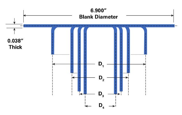
Assume that a 6.900-in.-dia. blank, with a nominal thickness of 0.038 in., must be reduced to a 2.100-in.-dia. cup (Fig. 1). From the draw-reduction table, the recommended reduction ratios for 0.038-in.-thick material are 44, 26 and 24 percent. To minimize the number of reductions, the designer decides to apply these recommended values:
Blank diameter = 6.900 in.
First draw (D1) 44 percent = 3.864 in.
Second draw (D2) 26 percent = 2.859 in.
Third draw (D3) 24 percent = 2.173 in.
After three reductions, the shell diameter measures 2.173 in. Achieving the desired diameter of 2.100 in. requires an additional 0.073-in. reduction. The designer may decide to add a ‘sizing’ station to achieve the final size, or increase the first draw reduction to 46 percent to achieve the final diameter in three reductions. Although both approaches may work, neither represents an ideal solution.
Draw-reduction tables provide recommended maximums, assuming that ideal process conditions exist in regard to material properties, blankholder pressure, lubrication conditions, drawing speeds, etc. Larger reductions, though possible, may cost more money over the life of the die to control and manage the process variables than would the additional costs be for adding more die stations.
 Another common problem involves the size of the punch-nose and die-entry radii. A tendency exists to make the radius too small, as making the radius larger during die tryout proves easier than trying to make it smaller. But doing so places needless stress into the cup, resulting in excessive thinning or fracturing. The problems associated with improper reduction percentage or improper die radius in the first draw station may not show up in that station, but in a later redraw station, leading to considerable time spent trying to fix the wrong station.
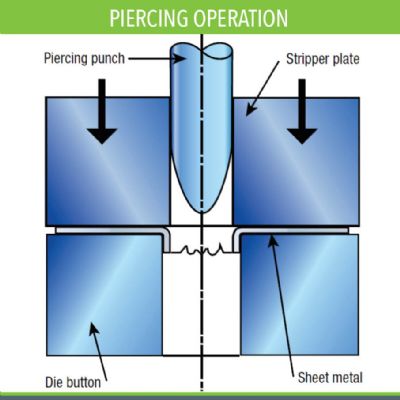

 Webinar